
 http://www.sgi.com/tech/openGL/paper/subsection3_4_1.html (Silicon Surf Promotional CD, 01/1995)
In OpenGL, most geometric objects are
drawn by enclosing a series of coordinate sets that
specify vertices and optionally normals,
texture coordinates,
and colors between glBegin/glEnd command pairs.
For example, to specify a triangle with vertices at
,
, and
, one could write:
glBegin(GL_POLYGON);
  glVertex3i(0,0,0);
  glVertex3i(0,1,0);
  glVertex3i(1,0,1);
glEnd();
The ten geometric objects that are drawn this way are summarized in Table 4.1. This particular group of objects was selected because each object's geometry is specified by a simple list of vertices, because each admits an efficient rendering algorithm, and because it was determined that taken together these objects satisfy the needs of nearly all graphics applications.
Each vertex may be specified with two, three, or four coordinates (four coordinates indicate a homogeneous three-dimensional location). In addition, a current normal, current texture coordinates, and current color may be used in processing each vertex. OpenGL uses normals in lighting calculations; the current normal is a three-dimensional vector that may be set by sending three coordinates that specify it. Color may consist of either red, green, blue, and alpha values (when OpenGL has been initialized to RGBA mode) or a single color index value (when initialization specified color index mode). One, two, three, or four texture coordinates determine how a texture image maps onto a primitive.
Each of the commands that specify vertex coordinates, normals, colors, or texture coordinates comes in several flavors to accomodate differing application's data formats and numbers of coordinates. Data may also be passed to these commands either as an argument list or as a pointer to a block of storage containing the data. The variants are distinguished (in the C language) by mnemonic suffixes.
Most OpenGL commands that do not specify vertices and associated information may not appear between glBegin and glEnd. This restriction allows implementations to run in an optimized mode while processing primitive specifications so that primitives may be processed as efficiently as possible.

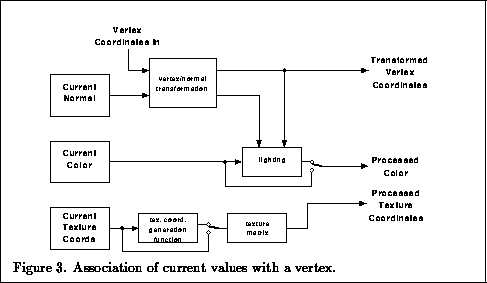
When a vertex is specified,
the current color, normal, and texture coordinates are used to obtain
values that are then associated with the vertex (Figure 2).
The vertex itself is transformed by the model-view matrix,
a matrix which can represent both linear
and translational transformations.
The color is obtained from either computing a color from lighting or,
if lighting is disabled, from the current color.
Texture coordinates are similarly passed through a texture coordinate
generation function (which may be the identity).
The resulting texture coordinates are transformed by the
texture matrix (this matrix may be used to effectively scale
or rotate a texture that is applied to a primitive).
Figure 4 shows some results of using texture coordinate generation functions.
A number of commands control the values of parameters used in processing a vertex. One group of commands manipulates transformation matrices; these commands are designed to form an efficient means for generating and manipulating the transformations that occur in hierarchical 3D graphics scenes. A matrix may be loaded or multiplied by a scaling, rotation, translation, or general matrix. Another command controls which matrix is affected by a manipulation: the model-view matrix, the texture matrix, or the projection matrix (to be described presently). Each of these three matrix types also has an associated stack onto which matrices may be pushed or popped.
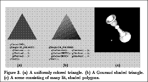
Lighting parameters are grouped into three categories: material parameters, that describe the reflectance characteristics of the surface being lit, light source parameters, that describe the emission properties of each light source, and lighting model parameters, that describe global properties of the lighting model. Lighting is performed on a per-vertex basis; lighting results are eventually interpolated across a line segment or polygon. The general form of the lighting equation includes terms for constant, diffuse, and specular illumination, each of which may be attenuated by the distance of the vertex from the light source. A programmer may sacrifice realism in favor of faster lighting calculations by indicating that the viewer, the light sources, or both should be assumed to be infinitely far from the scene. Figure 3 shows some results with lighting disabled and enabled.
