The first step when developing an object-oriented application based on the ViewKit framework is to identify a set of objects that can be used to construct the program. There are many ways to design an object-oriented system, but one common approach is somewhat analogous to functional decomposition, a common design technique used with traditional programming styles. In functional decomposition, a programmer starts with a single function and breaks it down into multiple functions. The process is usually repeated until many small, easily understood functions have been identified. In object-oriented decomposition, the starting point is a large-scale object that can be broken down into smaller objects. For example, an automobile is an object that contains many smaller objects - an engine, a body, a chassis, and so on. These objects can be decomposed further. For example, an engine has valves, pistons, and so on. Programs can usually be organized in a similar way.
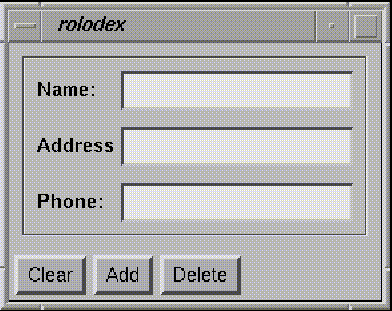
A mock-up of the user interface can be a useful place to start the design of an interactive application, because it is common for some parts of a program to correspond to logical groupings of elements of the user interface. For example, Figure 7 shows a proposed user interface for an overly-simplified address book program named rolodex.

Figure 7. User interface for the rolodex program.
Looking at the proposed rolodex interface, one can observe several logical user interface components. First, it might be useful to encapsulate the entire panel in a class that can be instantiated whenever a rolodex is needed. (The interface in Figure 7 looks like a stand-alone program, but it is easy to imagine an application that might use a rolodex as just one of many useful facilities.) So, it seems reasonable to create a Rolodex class as a ViewKit component.
The Rolodex class can be decomposed further. The screen shows a logical address area, and a command panel along the bottom. These can be implemented as Address and Command classes. The Address object consists of individual labeled text areas, which could each be implemented as a still smaller component, a LabeledText class.
Besides the user interface, there must be some way to store the information associated with the rolodex, so we might create a Database class. It might also be useful to abstract the information stored in the database, so a Record class could be created to represent a single name and address. So, the list of classes that can be used to construct the rolodex program include the Command, Address, LabeledText, Database, and Record classes. All these classes work together to form a subsystem that forms a single logical user interface component, bound together by the Rolodex class.
The next step is to determine the interfaces between the various objects. For the best results, these interfaces should be based on the role the object plays in the system, and have little to do with internal implementation details. For example, the Address class might support member functions for clearing the current display, displaying a new record, and creating a record from the information typed in by a user. The Command object simply sends messages to other objects. For example, the Command object might send a "clear" message to the Address object, an "add" message to the Database object, and so on.
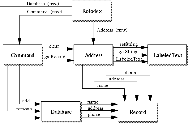
Figure 8 illustrates the architecture of the resulting system, by diagramming the messages that flow between objects in the system. This diagram shows all the classes used in the Rolodex example as boxes. The labeled vectors between the classes indicate member function calls (messages) that could occur between objects instantiated from these classes. Figure 8 clearly shows the relationships between the classes that implement the rolodex user interface component.
Once an initial design has been developed, the individual classes can be implemented. Many of these classes can be implemented as subclasses of the VkComponent class. The modular design makes it easy to extend or modify the system if needed. The new classes will fit smoothly with existing ViewKit classes to form a complete application.

Figure 8. A message diagram of the rolodex subsystem.
___________________________________________________________________